Pull Down Resistor Piezo
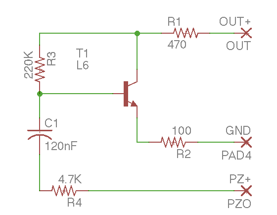
Pulldown resistor r3 the negative input of the opamp and the piezo element on t3 are very high impedance and would float if not pulled down. The first factor is power dissipation.

Piezo Circuit Issues Electrical Engineering Stack Exchange

Pull Up Resistor Basics Motion Control Tips

Pull Up Resistor For 555 Timer Ic Electrical Engineering
Tonemelody play a melody with a piezo speaker.

Pull down resistor piezo. If the resistance value is too low a high current will flow through the pull up resistor heating the device and using up an unnecessary amount of power when the switch is closed. This example demonstrates the use of pinmodeinputpullup. When i switch from one to the other i get a loud pop.
In addition the real opamp leaks a bit of charge into this terminal bringing it up to 60mv which is even above the switching threshold. I use a piezo pickup on my guitar in addition to the regular magnetic pickups. Using piezo vibration sensor with pull down resistor arduino.
This configuration causes the input to read. The other main component of the kit is the bag of 1m ohm resistors. This pull down resistor configuration is particularly useful for digital circuits like latches counters and flip flops that.
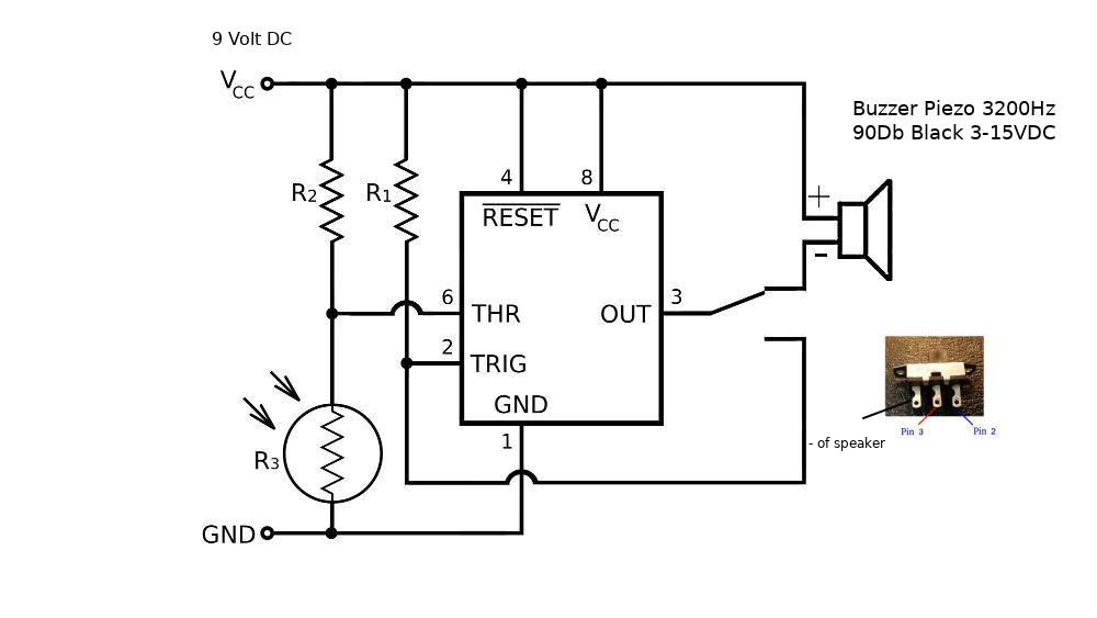
The 330 ohm resistor is connected in series to limit the current to the led. Ive asked this question on all sorts of forums with no real answer. An internal 20k ohm resistor is pulled to 5v.
Digital input pull up resistor. Thanks for your time. A pull down resistor works in the same way as the previous pull up resistor except this time the logic gates input is tied to ground logic level 0 low or it may go high by the operation of a mechanical switch.
The appropriate value for the pull up resistor is limited by two factors. Unlike pinmodeinput there is no pull down resistor necessary. What is a pull up and pull down resistor.
The pull down resistor value is 10 kilo ohm and the remaining components are 330 ohm resistor and led. Piezo elements come in lots of shapes and sizes but the ones in your kit are well suited for detecting a hit or finger press. A pull up resistor is used to make the default state of the digital pin as high or to the logic level in the above image it is 5v and a pull down resistor does exactly opposite it makes the default state of the digital pin as low 0v.
Ask question asked 6 years 7 months ago. The circuit diagram of the and gate using 2 pull down resistors at the ips to the and gate is shown below. So using a 1meg resistor with the piezo is essentially a 1meg source impedance which is far away from a good situation and as youve observed results in drift.
Would adding a pull down resistor help stop this. These are used in parallel with the piezo elements as pull down resistors to ensure a good read of the voltage produced by the element.

Getting Started With Matlab Support Package For Arduino

Mr Blinky On Twitter I M Just Wondering Why Did You Choose

Understanding The Pull Up Pull Down Resistors With Arduino

Turning Pc On With A Knock Using Attiny45 And A

Connecting Piezo Vibration Sensor To Launchpad General 43oh

High Voltage Amplifiers Falco Systems

Resistors Archives Circuits Diy

Understanding Common Collector Amplfier For A Piezoelectric

Playing Melodies On Piezo Buzzer Using Arduino Tone Function

Raspberry Pi Accessories Piezo Speaker Poweroff Led
Pjrc Teensy Forum

Making Sense Out Of Sensors Ppt Download
Comments
Post a Comment